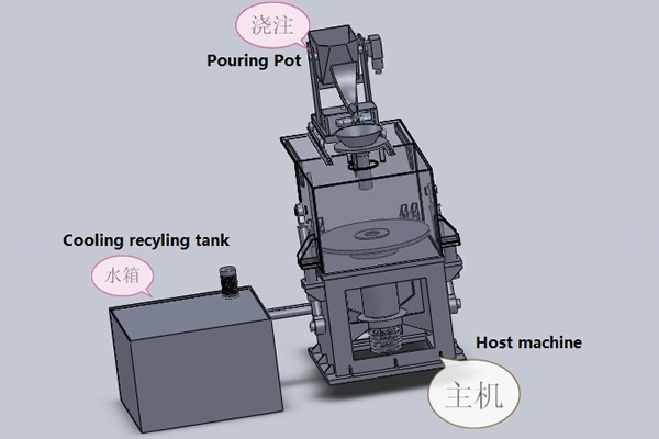
centrifugal casting machine of water pipes in sand-lined molds
centrifugal casting machine of water pipes in sand-lined molds
The rails are turned through 90 ~ by means of the disc (5), which moves in the direction Indicated by arrows,
and the supporting roller (7). The shaft (6) of the disc is attached to the slide bar (3) which Is moved on the parallel
guides (4) by means of the piston and connecting rod (2). The stroke of the slide bar is 400-500 ram. The
device is driven by compressed air In the cylinder (1). The disc and the supporting roller revolve freely under
the action of friction between their surfaces and the surface of the moving rail.
The diagram shows the position of the disc, the supporting roller, and the rail being turned, at the initial
stage of the turning operation; the base of the raft rests with the flange against the supporting roller, the disc
is moved to the right and so turns the rail Compressed air change is effected at the control desk by means of an
electromagnetic valve.
The device proved to be suitable for turning any type of rail of various lengths.
The turning of rails on the gag press. The turning collar (Fig. 3), employed for turning rails on gag presses,
is reliable in operation and fully satisfies the needs in this section.
The rail to be placed on the gag press is firmly held in the collarby the gripping roller. In the course
of rail straightening, the collar is rotated by the electric motor through a worm gear. A shock absorber protects
the turning equipment from shocks during rail straightening.
The turning collaz is made suitable for turning rails of all types manufactured at the works.
The main advantages of this design are the compactness, ease of operation and maintenance, reliability
tn operation, and high throughput.
With a coordinated operation of the adjoining units (milling, drilling, and hardening machines) the gag
press equipped withthe turning collar shows a throughput of 450 or more 25-m-long R-50 rails per shift.

